

Introduction:
In the realm of water quality monitoring, creating a TDS (Total Dissolved Solids) meter can be both educational and practical. In this blog post, we're delving into the fascinating world of DIY electronics as we guide you through the process of building a TDS meter using the ESP8266 microcontroller, a DFRobotics Gravity TDS sensor, a DALL temperature sensor, and a Blynk app for remote monitoring. By the end of this guide, you'll have a functional TDS and temperature monitoring system that can provide valuable insights into water quality.

What is TDS and Why is it Important?
TDS stands for Total Dissolved Solids, which refers to the sum of all inorganic and organic substances present in water in a dissolved form. These substances can include minerals, salts, metals, and other contaminants. TDS is a crucial indicator of water quality, as it can affect taste, health, and the performance of appliances. Monitoring TDS levels helps assess water's suitability for consumption and various applications.
Prerequisites:
Before you dive into this hands-on project, gather the following components:
ESP8266 Board: A WiFi-enabled microcontroller.
DFRobotics Gravity TDS Sensor: For measuring Total Dissolved Solids.
DALL Temperature Sensor: To measure water temperature.
I2C LCD Display: For visualizing data.
Blynk App Account: Set up an account on the Blynk platform.
Jumper Wires: For connecting the components.
Arduino IDE: The platform for programming and code upload.
Project Overview:
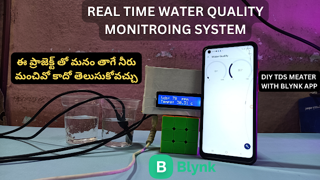
The aim of this project is to create a TDS and temperature monitoring system using the ESP8266 microcontroller. The DFRobotics Gravity TDS sensor will measure the water's TDS level, while the DALL temperature sensor will provide temperature readings. The collected data will be displayed on an I2C LCD display and can be remotely monitored using the Blynk app.
Circuit:

Code:#define BLYNK_TEMPLATE_ID "TMPLPvL6sVUg"#define BLYNK_TEMPLATE_NAME "water quality"#define BLYNK_AUTH_TOKEN "iUK2MNhZBLVpPNHSEX2A6RtcAKjhSLJI"
// Comment this out to disable prints and save space#define BLYNK_PRINT Serial#include <BlynkSimpleEsp8266.h>#include <ESP8266WiFi.h>#include <WiFiClient.h>#include <LiquidCrystal_I2C.h>#include <Wire.h>#include <OneWire.h>#include <DallasTemperature.h>
LiquidCrystal_I2C lcd(0x27, 16, 2); // Your WiFi credentials.// Set password to "" for open networks.char ssid[] = "mewt";char pass[] = "87654321";
char auth[] = BLYNK_AUTH_TOKEN;
namespace pin {const byte tds_sensor = A0;const byte one_wire_bus = 2; // Dallas Temperature Sensor}
namespace device {float aref = 3.3; // Vref, this is for 3.3v compatible controller boards, for arduino use 5.0v.}
namespace sensor {float ec = 0;unsigned int tds = 0;float waterTemp = 0;float ecCalibration = 1;}
OneWire oneWire(pin::one_wire_bus);DallasTemperature dallasTemperature(&oneWire);
void setup() { Serial.begin(9600); // Dubugging on hardware Serial 0 lcd.init(); lcd.backlight(); Blynk.begin(auth, ssid, pass); dallasTemperature.begin();
delay(2000);
}
void loop() { Blynk.run(); readTdsQuick();
delay(1000);}
void readTdsQuick() { dallasTemperature.requestTemperatures(); sensor::waterTemp = dallasTemperature.getTempCByIndex(0); float rawEc = analogRead(pin::tds_sensor) * device::aref / 1024.0; // read the analog value more stable by the median filtering algorithm, and convert to voltage value float temperatureCoefficient = 1.0 + 0.02 * (sensor::waterTemp - 25.0); // temperature compensation formula: fFinalResult(25^C) = fFinalResult(current)/(1.0+0.02*(fTP-25.0)); sensor::ec = (rawEc / temperatureCoefficient) * sensor::ecCalibration; // temperature and calibration compensation sensor::tds = (133.42 * pow(sensor::ec, 3) - 255.86 * sensor::ec * sensor::ec + 857.39 * sensor::ec) * 0.5; //convert voltage value to tds value Serial.print(F("TDS:")); Serial.println(sensor::tds); Serial.print(F("EC:")); Serial.println(sensor::ec, 2); Serial.print(F("Temperature:")); Serial.println(sensor::waterTemp, 2); lcd.setCursor(0, 0); lcd.print("tds: "); lcd.print(sensor::tds); lcd.print(" ppm");
lcd.setCursor(0, 1); lcd.print("Tempe: "); lcd.print(sensor::waterTemp); lcd.print(" c");
Blynk.virtualWrite(V0, (sensor::tds));
Blynk.virtualWrite(V1, (sensor::waterTemp));}
Understanding TDS Levels for Drinkable Water:

TDS levels are often used to assess water quality and its suitability for consumption. Generally, lower TDS levels (below 300 ppm) are preferred for drinking water, as they indicate fewer dissolved contaminants. Water with high TDS levels may have an unpleasant taste and could potentially contain harmful substances. It's important to check local water quality guidelines and standards to determine safe TDS ranges for your area.
Conclusion:
With the ESP8266, DFRobotics Gravity TDS sensor, DALL temperature sensor, and Blynk app, you've successfully constructed a TDS and temperature monitoring system. By visually displaying water quality data and enabling remote monitoring, you're not just delving into electronics but also contributing to practical applications. This project not only enhances your technical skills but also empowers you to make informed decisions regarding water quality. So, gather your components, follow the steps outlined in this guide, and embark on the journey of creating a TDS meter that can bring water quality insights to your fingertips.


0 Comments